Housing v2: split PETG housing for the CYD (USB-C variant)
Three printed parts, four screws, four inserts. The step-by-step build (buying the board, inserts, assembly, with pictures) is in build guide; the parts list as a spreadsheet is BOM.csv. Only the USB-C port is exposed; the light sensor gets a
clear light pipe so the firmware's ambient-light features still work behind a closed lid. Designed in
Fusion 360 by WOODWERD LLC; STL for printing, STEP if you want to modify it. This is housing v2 — printed, test-fitted on a USB-C board, and the released design.
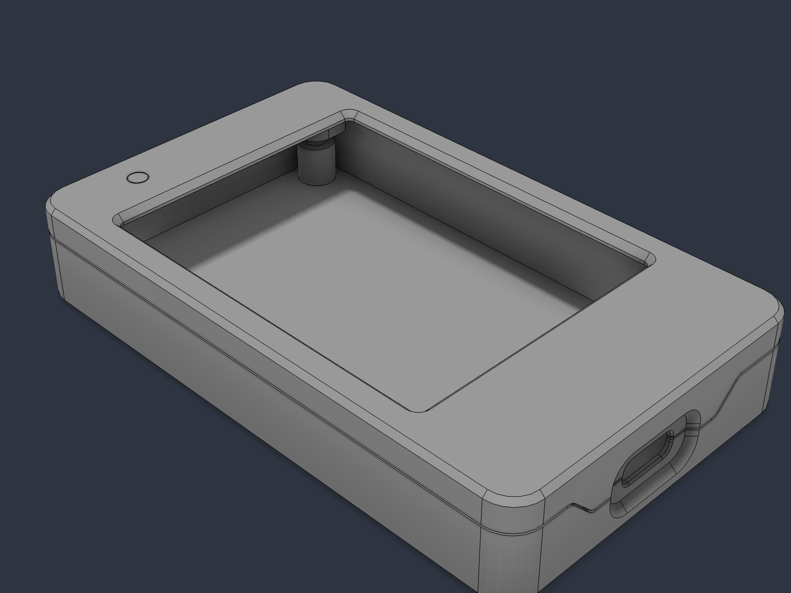
| File | Part | Qty | |
|---|---|---|---|
CYD_Case_v2_Base.stl |
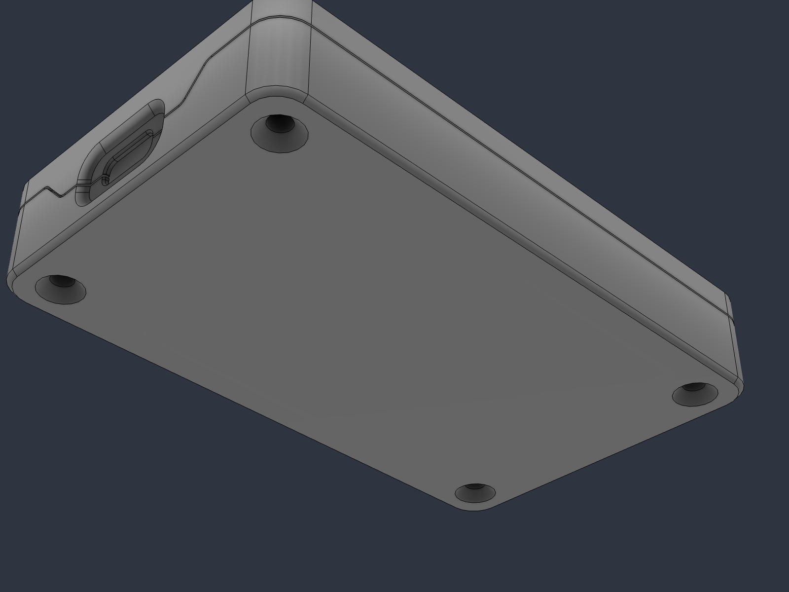
Base — board drops in USB-C end first, screws from below | 1 | open side up, no supports |
CYD_Case_v2_Lid.stl |
Lid — display window, insert bosses, USB-C tongue | 1 | face down on the bed, no supports |
CYD_Case_v2_LightPipe.stl |
Light pipe for the LDR — Ø2.9 rod on a Ø5 flange | 1 | clear filament, flange down, 100 % infill |
Download the files: housing v2 on GitHub, STL for printing and STEP for editing.
Outer size 54.6 × 90.6 × 16.1 mm. Wall 2.0 mm, 0.3 mm clearance per side around the board. Volumes: base 15.2 cm³, lid 5.4 cm³.
Print settings that matter
- Material: PETG recommended (heat-set inserts seat cleanly; PLA works at a lower iron temperature).
- Layer height: 0.2 mm (0.16 for a nicer display chamfer). 3–4 perimeters so the lip and groove are solid.
- No supports on any part. The USB-C funnel is a 45° loft and the port hole is bridged by the tongue.
- Tolerances: the lid rides on a 0.9 mm lip with 0.15 mm lateral clearance and a designed 0.3 mm parting-line gap outside. If your printer runs fat, a −0.1 mm horizontal expansion (XY compensation) on the lid is the first thing to try. If a USB-C cable won't click home, the local wall at the port is 0.8 mm — sand the lead-in chamfer before reprinting.
- Test print first: the base alone, and try a cable in it. That's the only fit that matters.
Hardware (BOM)
| Qty | Part | Spec |
|---|---|---|
| 4 | M3 × 14 mm flat-head screw, 90° countersunk, hex socket | DIN 7991 / ISO 10642. Not M3 × 16 — the tip would reach the lid face. |
| 4 | M3 brass heat-set insert, 4 mm long, OD 4.0–4.2 | The "M3 × L4" kit size (Voron M3×5×4 also fits). 5.7 mm inserts bottom out. |
| 1 | Cheap Yellow Display USB-C / 2-USB variant (ESP32-2432S028R with Type-C) | The micro-USB-only board also fits mechanically but its port is covered. |
Full fastener sheet with a section drawing: Fastener_Spec.pdf.
Assembly
- Heat-set the four inserts into the lid bosses — soldering iron with an M3 insert tip, ~230 °C for PETG (~200 °C for PLA), press to flush, let cool. Do this before the board goes in.
- Push the light pipe up into its tube on the lid ceiling from inside, flange against the ceiling.
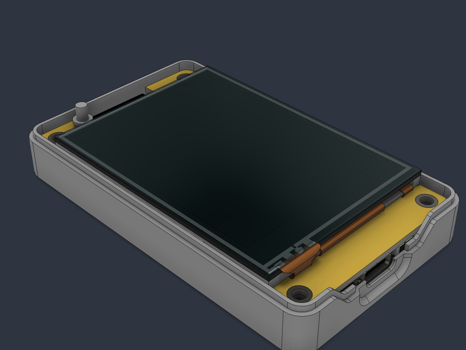
- Flash the board first (it's easier with it out of the case), then drop it into the base, USB-C end first.
- Lid on: tongue into the slot over the port, lip into the groove. Four screws from below, snug only — it's plastic.
What's covered / open
- Exposed: USB-C, light sensor (via pipe), display, touch.
- Covered: micro-USB, microSD, RST/BOOT buttons, JST headers, RGB LED (it may show through light-coloured filament). Housing v3 (in development) opens the microSD slot and adds RESET / BOOT buttons.
Modifying
*.step files are exact geometry. All corner radii are concentric with the board's R2.5 corners
(centres at ±22.5, ±40.5 mm from the board centre); the split is at z 2.5 mm above the PCB underside.