Build guide: parts, printing, inserts, assembly
This guide covers housings v2 and v3. They share the hardware and the steps; where v3 differs, it says so. The steps are the same for every WOODWERD CYD firmware; only the flashing step differs, and each project's own docs cover that.
Everything from ordering the parts to having the case on your desk. Nothing here needs soldering beyond a soldering iron used as a heat source for the inserts. Budget an evening: an hour of printing you don't have to watch, twenty minutes at the bench.
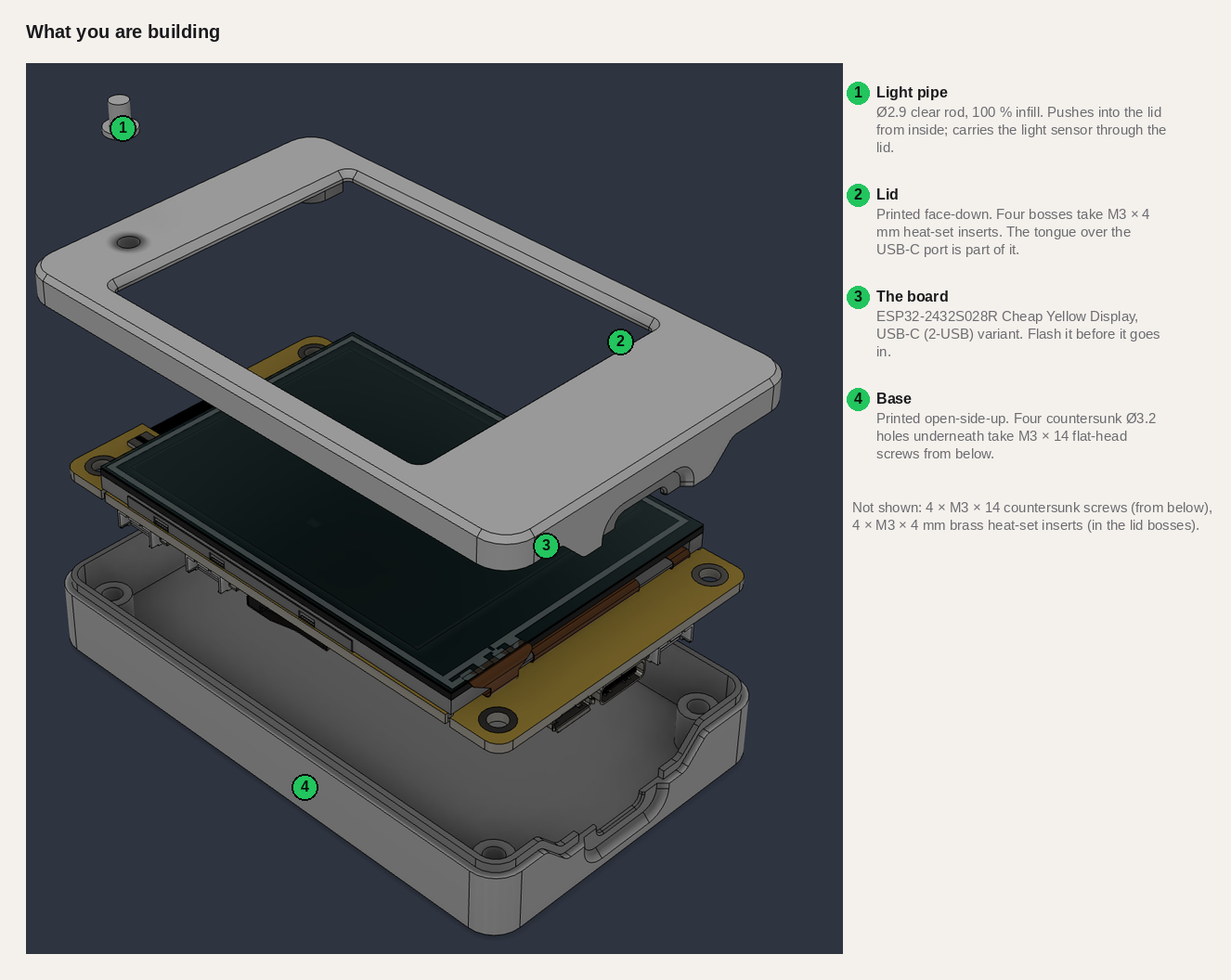
Bill of materials
| # | Qty | Part | Spec | Notes |
|---|---|---|---|---|
| 1 | 1 | Cheap Yellow Display board | ESP32-2432S028R, 2.8" 320 × 240 touch, USB-C (2-USB) variant | The case only exposes USB-C — buy the version that has a USB-C port |
| 2 | 1 | USB-C cable, data | USB-C → USB-A recommended | Some boards lack CC resistors; C-to-C into a Mac's C port may not power |
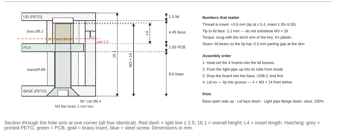
| 3 | 4 | Flat-head screw | M3 × 14 mm, 90° countersunk, hex socket, DIN 7991 / ISO 10642 | Length includes the head. Not M3 × 16. 2 mm hex key |
| 4 | 4 | Heat-set threaded insert | M3, brass, 4 mm long, OD 4.0–4.2 mm | The "M3 × L4" kit size; Voron M3×5×4 also fits. Not the 5.7 mm ones |
| 5 | 1 | Printed: Base | CYD_Case_v2_Base.stl or CYD_Case_v3_Base.stl, PETG, no supports |
open side up |
| 6 | 1 | Printed: Lid | CYD_Case_v2_Lid.stl or CYD_Case_v3_Lid.stl, PETG, no supports |
face down |
| 7 | 1 | Printed: Light pipe | CYD_Case_v2_LightPipe.stl (v3's is the same part), clear filament, 100 % infill |
flange down |
| — | — | Tools | soldering iron (insert tip or clean conical), 2 mm hex key, 3D printer |
Same list as a spreadsheet: BOM.csv. Fastener detail with a section
drawing: Fastener_Spec.pdf.

1 · Buy
| Qty | Part | What to look for | Where |
|---|---|---|---|
| 1 | ESP32-2432S028R "Cheap Yellow Display", USB-C variant | 2.8" 320 × 240 touch display with an ESP32 on the back. Listings say ESP32-2432S028R, CYD, or Cheap Yellow Display. Get the version with a USB-C port (it has both micro-USB and USB-C on the board; the community calls it "CYD2USB" or "2-USB"). The case only exposes USB-C. | Amazon, AliExpress, Banggood — usually well under $20. Two-packs are common. |
| 1 | USB-C cable, data-capable | Any phone cable that syncs data works. Some CYD boards lack the CC resistors, so a USB-C → USB-A cable into an A port (or an A adapter) is the reliable choice; C-to-C into a Mac's C port sometimes gives no power. | you have one |
| 4 | M3 × 14 mm flat-head screw, 90° countersunk, hex socket | DIN 7991 / ISO 10642. Stainless or black oxide. Length 14 including the head — not 16, the tip would reach the lid face. 2 mm hex key. | any metric fastener kit or hardware store |
| 4 | M3 brass heat-set insert, 4 mm long, OD 4.0–4.2 mm | The "M3 × L4" size in most insert kits; Voron-style M3×5×4 also fits. Not the 5.7 mm ones — they bottom out in the boss. | insert kit, CNC Kitchen, Amazon |
| ~30 g | Filament, PETG recommended | Base and lid. PLA works (use a cooler iron for the inserts). | — |
| a scrap | Clear filament | For the light pipe. Transparent PETG or clear PLA. Natural/translucent works; opaque does not. | — |
Tools: a 3D printer (0.4 mm nozzle is fine) · a soldering iron, ideally with an M3 insert tip, a clean conical tip will do · a 2 mm hex key · optional calipers for sorting screws.
Is this screw M3? Hold the bare board over the bin: the screw that drops through a corner hole is
M3 (Ø3.0 thread, 5.5–6 mm head). M4 and M5 won't pass. The fastener sheet has a sorting table:
Fastener_Spec.pdf.
2 · Print
Files in housings/v2/ or housings/v3/. STL for slicing, STEP if you want to change something.
| File | Orientation | Notes |
|---|---|---|
CYD_Case_v2_Base.stl |
open side up | no supports; the countersinks are on the bed side and print clean |
CYD_Case_v2_Lid.stl |
face down | no supports; the display chamfer is on the bed, the bosses point up |
CYD_Case_v2_LightPipe.stl |
flange down | clear filament, 100 % infill, slow — it's a 5 mm part |
Settings that matter: 0.2 mm layers (0.16 for a nicer chamfer), 3–4 perimeters so the lip and groove are solid, PETG at your usual temperature, no supports on anything. Outer size 54.6 × 90.6 × 16.1 mm.
v3: turn on elephant-foot compensation for the base. The RESET and BOOT buttons are cut free by 0.6 mm slots that start on the bed, and a squashed first layer can bridge them. Check both buttons flex before you go on.
Print the base first and try a USB-C cable in it. That's the only fit that matters. If the plug won't click home, sand the lead-in chamfer a little; if your printer runs fat and the lid is tight on the base, a −0.1 mm horizontal-expansion (XY compensation) on the lid is the first knob to turn.
3 · Inserts
Do this before the board goes anywhere near the lid.
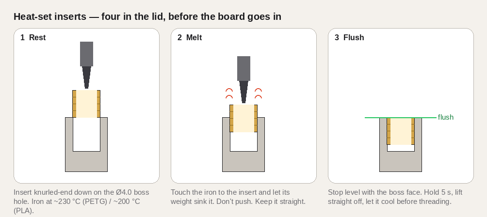
- Set the iron to ~230 °C for PETG (~200 °C for PLA).
- Rest an insert, knurled end down, on one of the four Ø4.0 mm holes in the lid bosses.
- Touch the iron to the insert and let the iron's weight press it in — don't push. Keep it straight.
- Stop when the insert is flush with the boss face. Hold 5 seconds, lift straight off.
- Let it cool before threading anything in. Repeat ×4.
If one goes in crooked, reheat and nudge it; the boss has room. This is where the insert and the screw sit in the finished stack — the screw comes up from the base, through the board, and gets about 3.9 mm of thread in the insert:
4 · Flash the board on the bench
Flashing is easier with the board out of the case. Use your project's own instructions: Flow Ctrl or ESP Ctrl for any image. Confirm the screen comes up before you close anything up. If the port doesn't show up, hold BOOT while plugging in.
5 · Assemble
- Push the light pipe up into its tube on the underside of the lid, flange against the ceiling.
- Drop the board into the base, USB-C end first, so the port seats in the lower half of its opening. Screen up. The four corner holes line up over the standoffs.
- Lid on: the tongue over the port goes into its slot, then the lip drops into the groove all the way round. It should seat with no force; if it doesn't, something's under it.
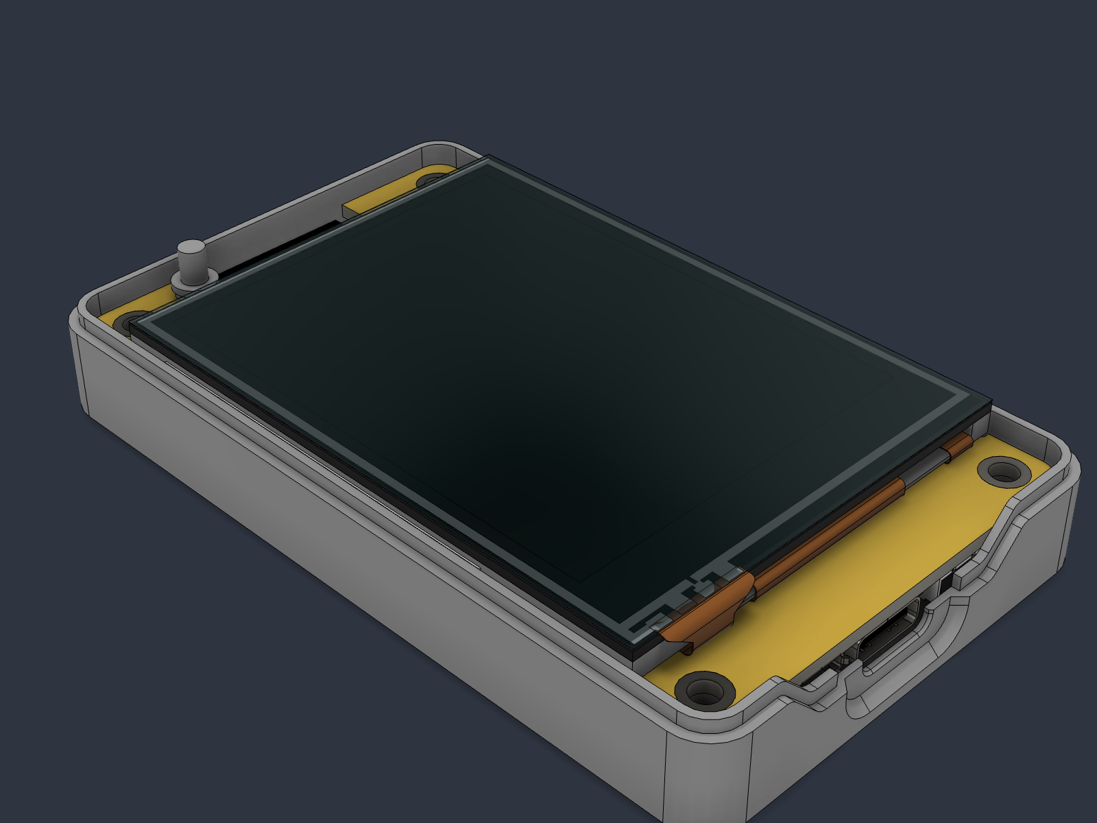
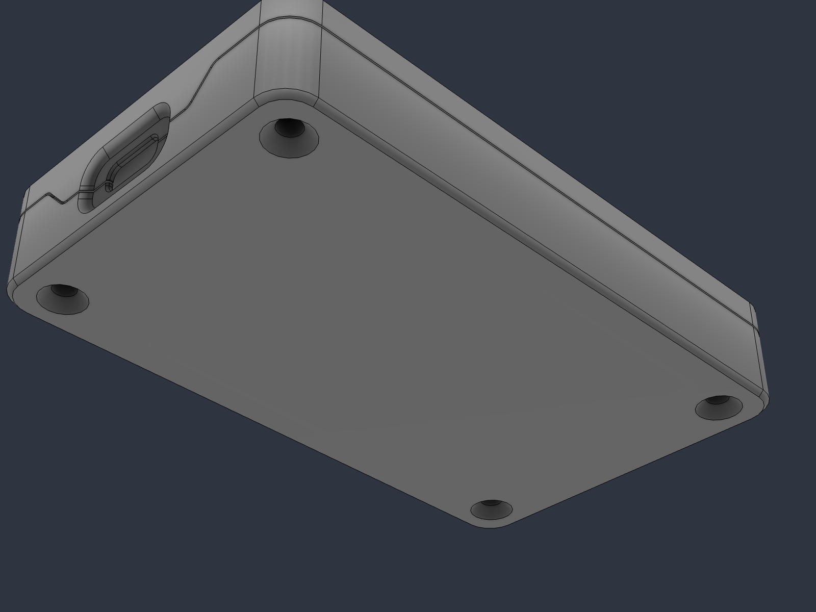
- Flip it over and drive the four M3 × 14 screws from below, 2 mm hex, snug with the short arm of the key. It's plastic — stop when the head sits in the countersink.
- v3: slide in a microSD card if your firmware uses one. Push until it clicks; push again to release it. Press RESET from below to restart the board; hold BOOT while pressing RESET for download mode.
6 · Then
Go back to your project's getting-started guide. The light sensor works through the pipe; the RGB LED may show faintly through lighter filament.
What's covered on purpose
On v2, micro-USB, the microSD slot, the RESET / BOOT buttons and the JST headers are all inside. Housing v3 opens the microSD slot and adds printed RESET and BOOT buttons. Micro-USB and the JST headers stay inside on both; the STEP files make small edits easy.